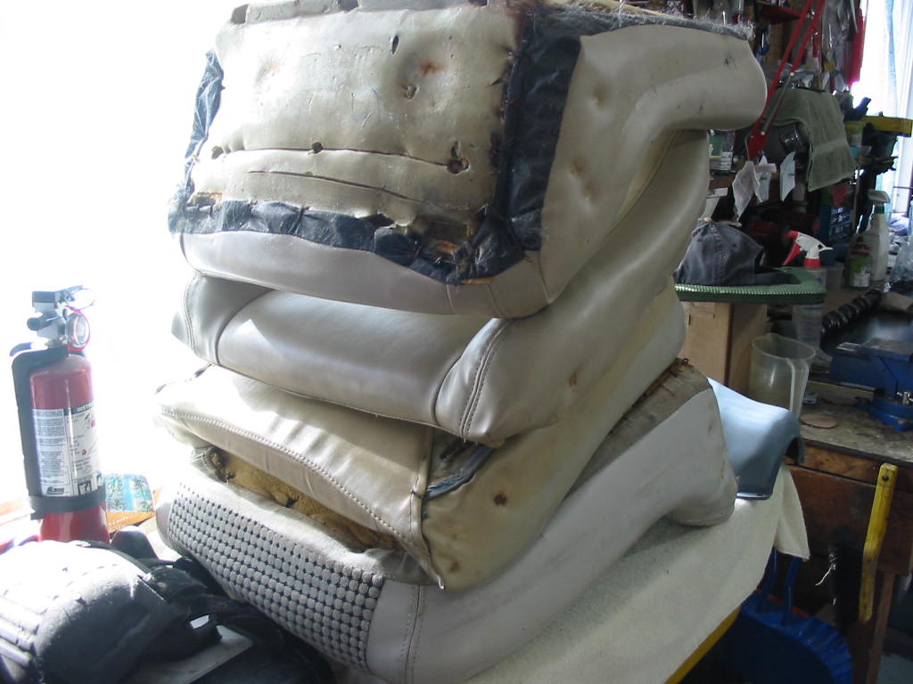
Seats out once again and cushions removed and ready to go the upholstery shop.
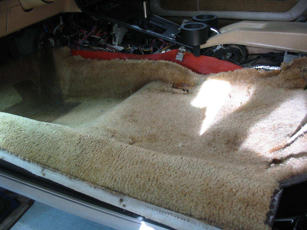
Besides the engine work, which I had not planned on, I was planning to add sound deadener to the interior panels. All the carpeting needs to be removed for that.
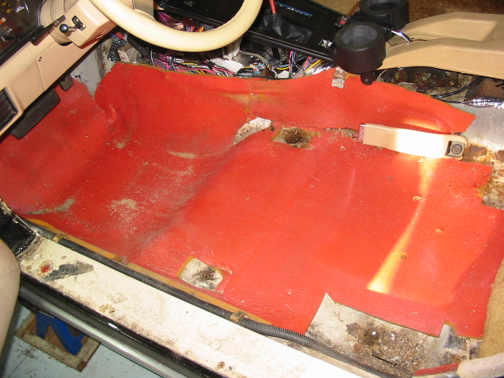
A previous owner had fitted 1/2″ foam to help keep the noise down. I’m told that foam is good for absorbing sound inside the car to keep it from reverberating, but you need heavier buytl like stuff to keep the sound from coming into the car.
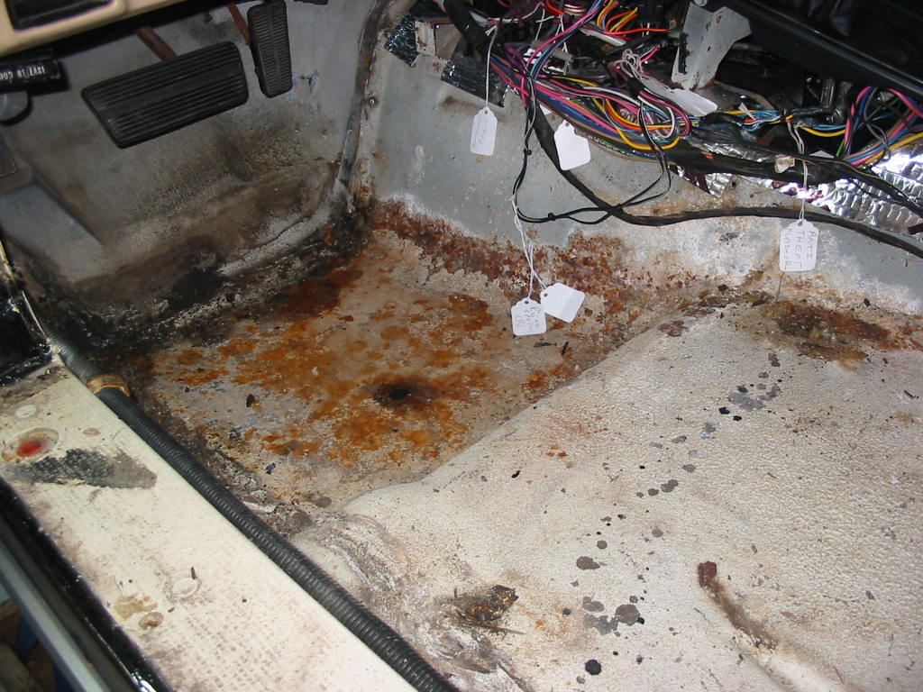
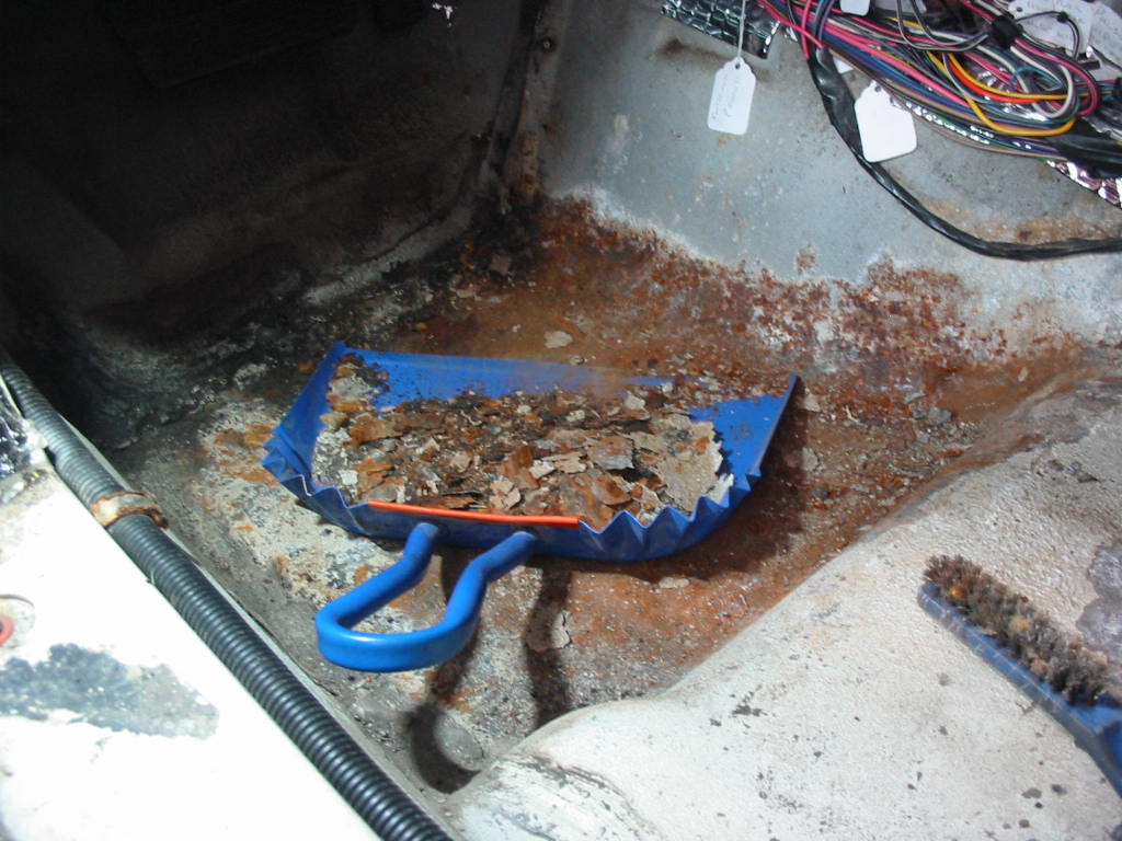
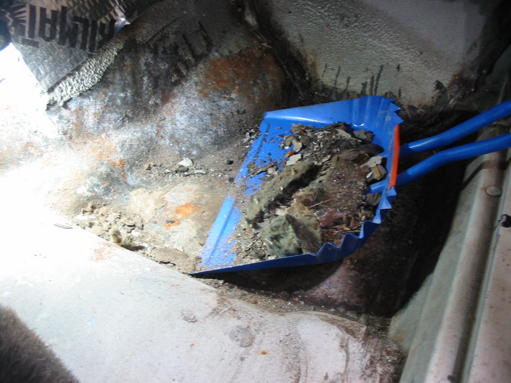
Lots of crud build up on the floors and most of the paint was loose from the fibreglass. At this point I am very happy that this model still had the fibreglass floors and not the metal one used later. The floors would have been toast as it looked like there had been a lot of moisture or even water present at some time.
Lots of scraping needed.
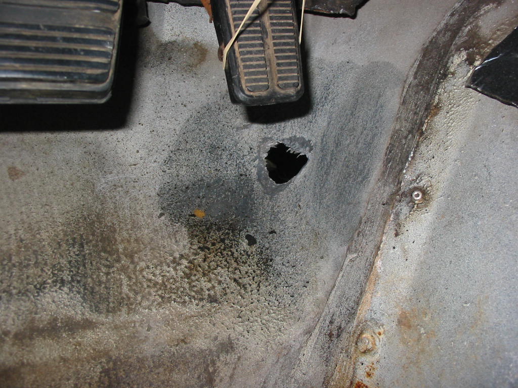
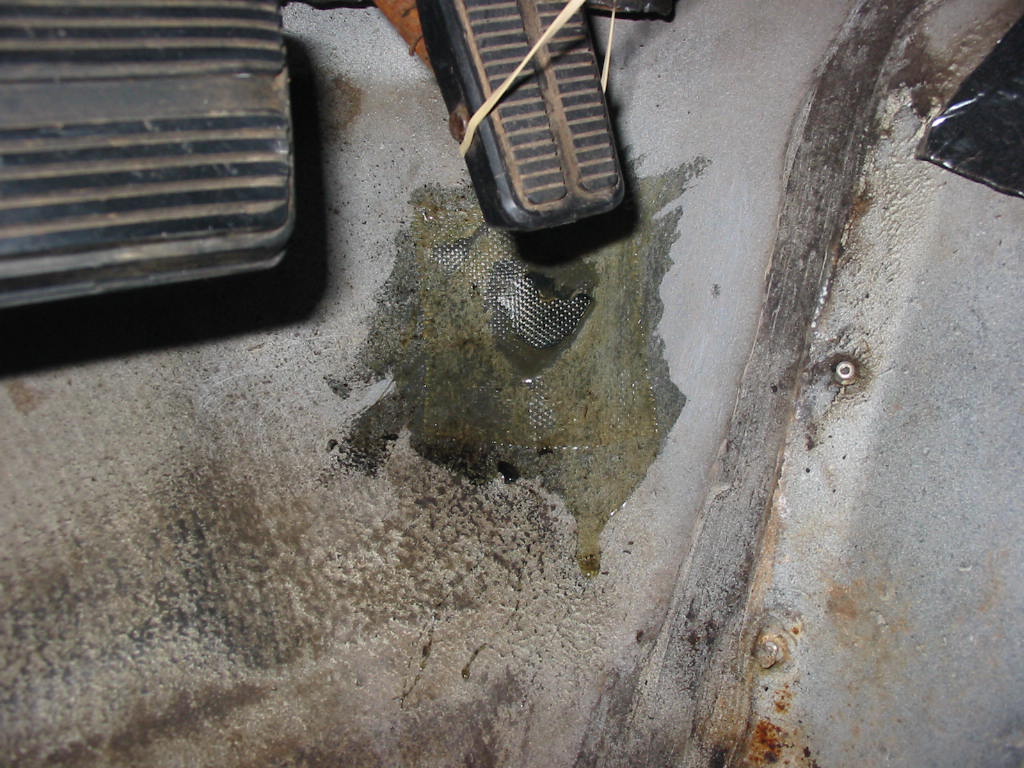
A lot of the seam sealer came away with the crud on the floors. Looks like a factory drain hole in the floor. I’ll keep that open just in case…
Not sure what happened here. The hole may have been there or maybe I did the damage moving engines in and out.
First layer of fibreglass in place. I’ll add another layer to the inside and then two to the outside.
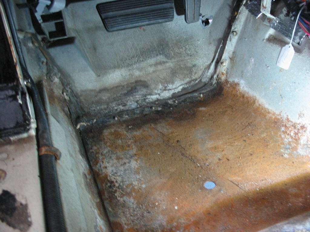
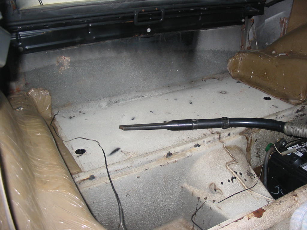
Ditto as to crud on the passenger side. Although a lot less paint peeled away.
Not showing was a layer of felt like material that was on the flat area and the back up to the security blind. The nice factory insulation over the wheel wells is still in place and in good shape.
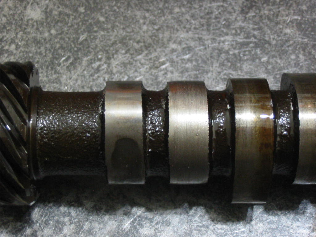
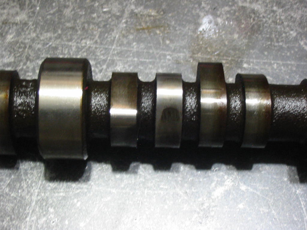
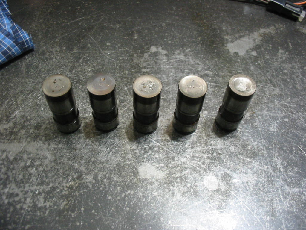
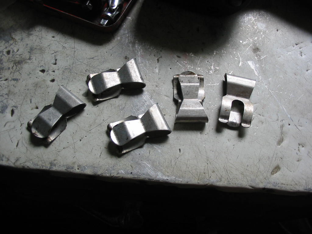
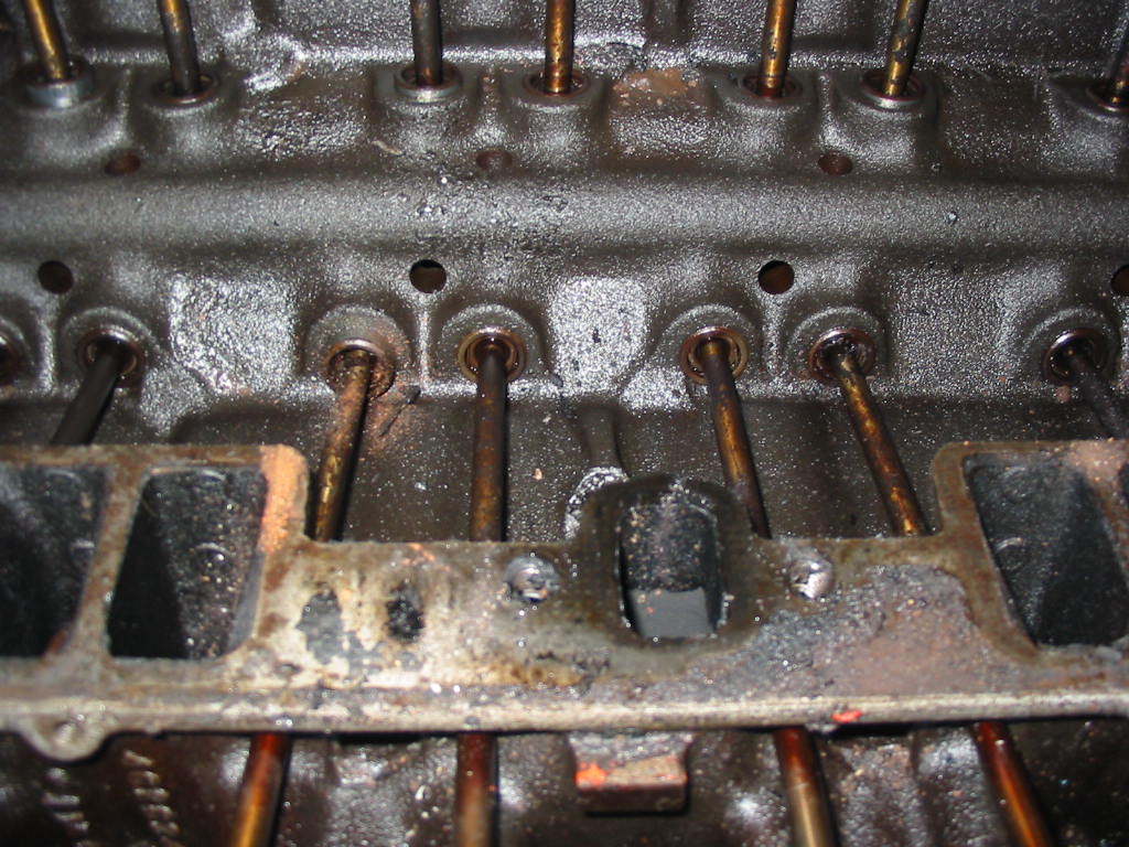
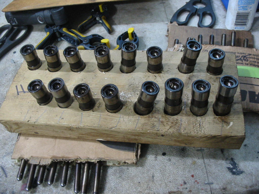
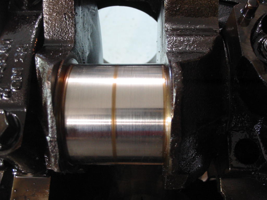
The top shot shows the nicely rounds cam lobe. The second shows another lobe on it’s way out (second lobe from the left)
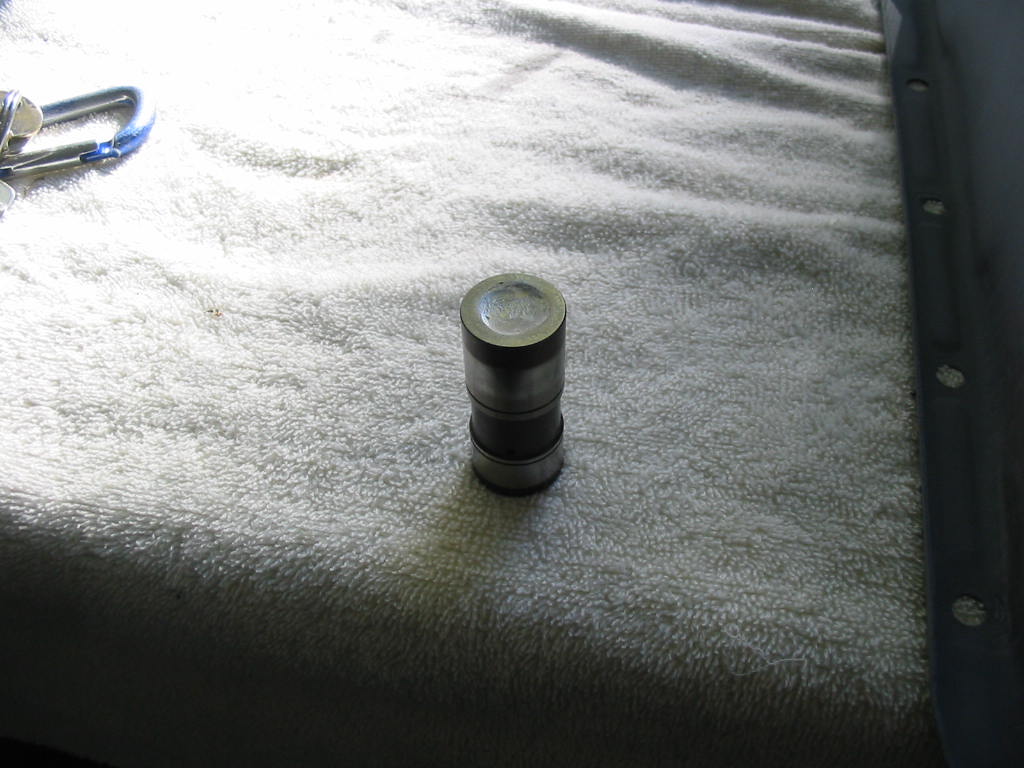
Lifter on the right is the one that ended the engine. Four others show that they are on the way out. Typical 305 soft cam problem. However, the original owner must have kept up with the maintenance to have the engine go over 200k.
So I’ll put it up for grabs including a used 350 cam and lifters in case anyone wants to use the motor. I had compression between 130 and 160 so not all that bad and it may have many miles on it yet.
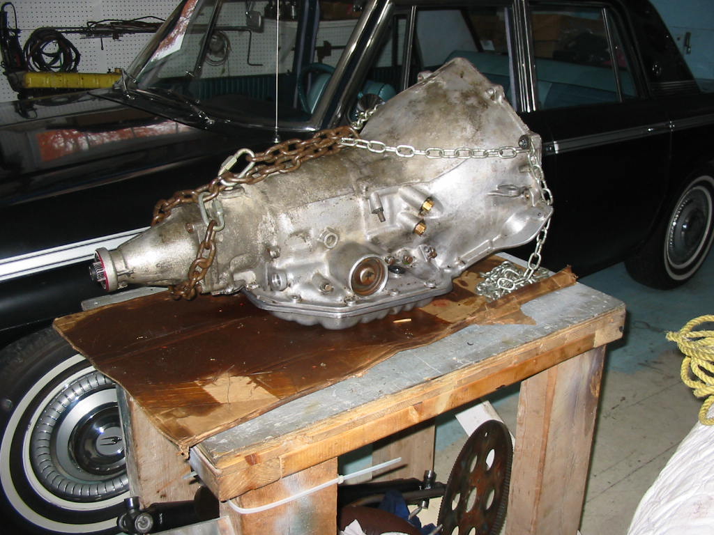
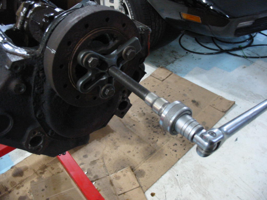
Trans emptied of oil and ready to go to the rebuilder. It actually went yesterday. I also found out then that it isn’t a TH350C but rather an TH250C. The band adjuster just behind the cooling line ports is the give away. The trans has a band for second gear rather than clutches. No matter. I won’t be putting undue stress on the trans and I like the fact that it has a lock-up converter.
Next: on to other things while I wait for the block, trans and new parts.
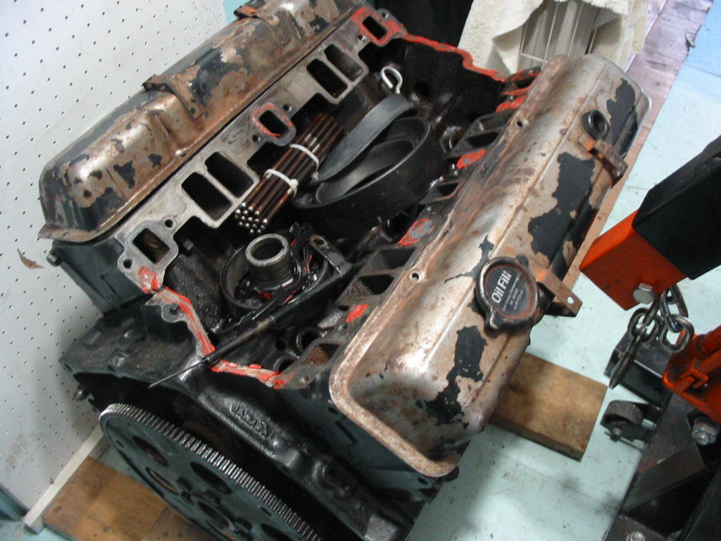
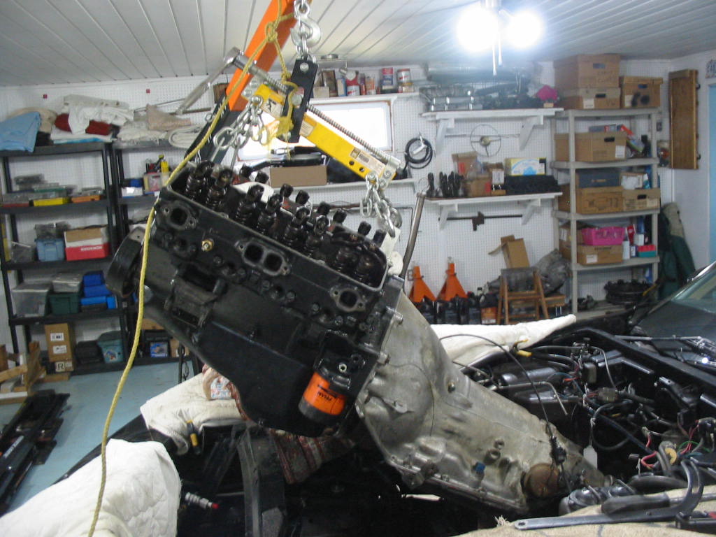
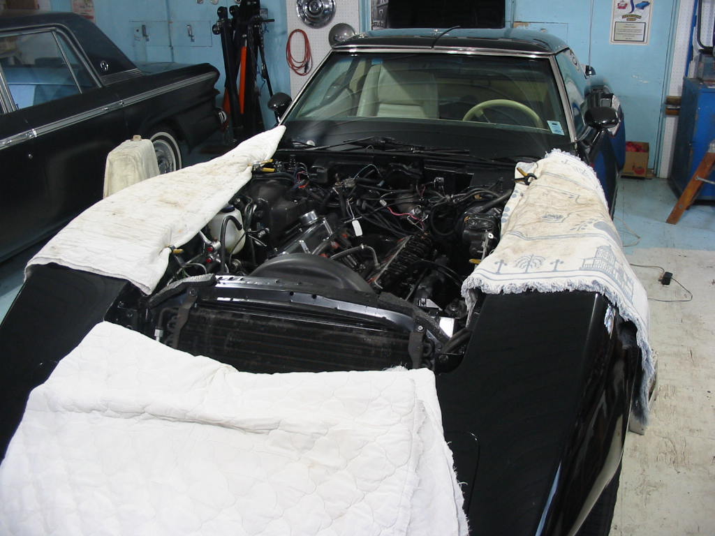
I couldn’t get the engine out of the car with the exhaust manifolds in place. They snagged on the exhaust pipes. Also I needed to remove the water pump and the crank pulleys.
The manifolds are smeared with oil because I forgot to use my oil clips. These mount on the pushrod end of the rockers and stop oil squirting out over the manifolds. I bought them long ago to help setting the solid lifters on the ’67 427 I had back in my hay-days.
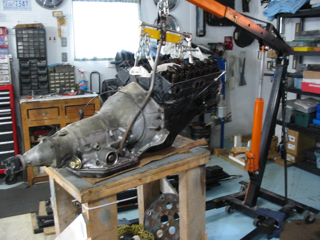
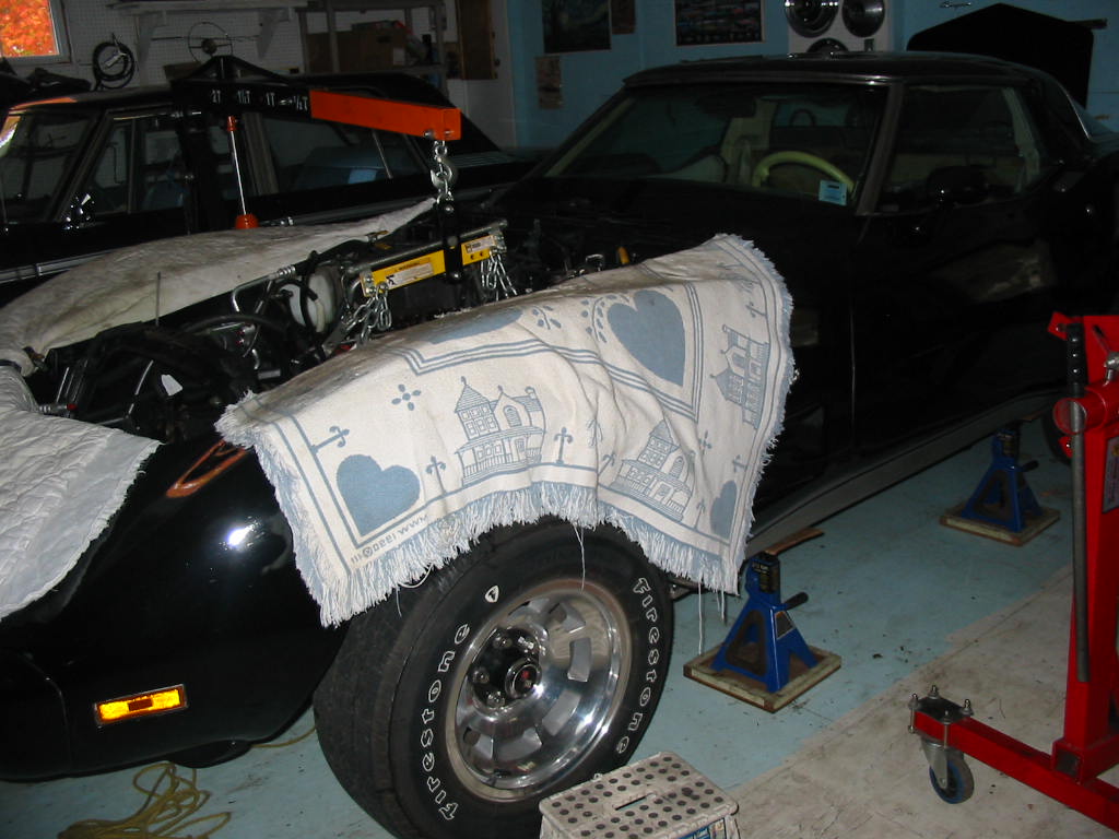
With those items off it came up quite easily using the adjustable lift mechanism. I did have some problems getting the engine to move forward off the rear trans mount until I realized that the upper bolts on the mount needed to be removed as it was also an attachment point for the exhaust mount. Once I got that out of the way it was a matter of slowly inching it forward and up until it cleared the rad frame.
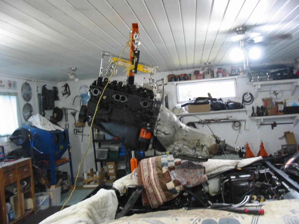
Fortunately I had just enough room under the ceiling to get the engine out of the car.
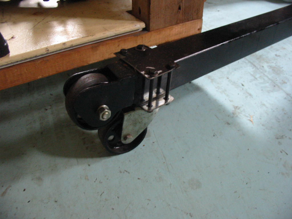
This is a shot of the caster wheels I put on the end of the engine lifter arms. They are metal and don’t swivel all that easily when the engine/trans are on the hoist. I ended up putting a rope one one end and pulling the leg out from under the car when I wanted to move the engine trans forward.
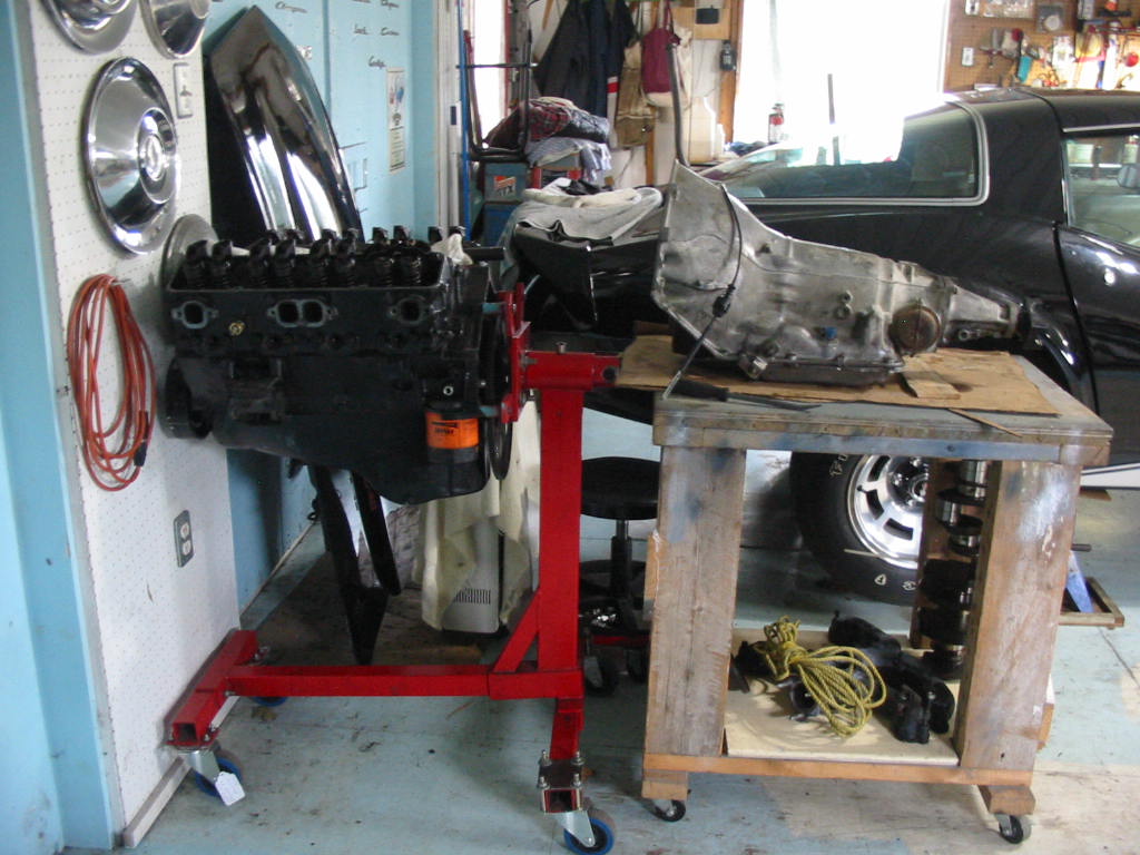
From here I’ll separate the engine from the trans and get it on an engine stand. I’ll then drain the trans and get it to a trans shop to be checked.
Engine and trans separated. Now I’ll get the fluids out of the trans and get it ready to go the Earl’s trans shop.
Next: replacing the cam and lifters on the 305 before it goes back to the original owner. His son wants to put it in their International Scout when they do a restoration on it. Personally I’d rebuild the Scout engine to keep that classic original, but many many folks want to stuff GM V8s in their trucks, cars and rods no matter what the make.
Once again I’m out of sequence. Hope this all makes sense.
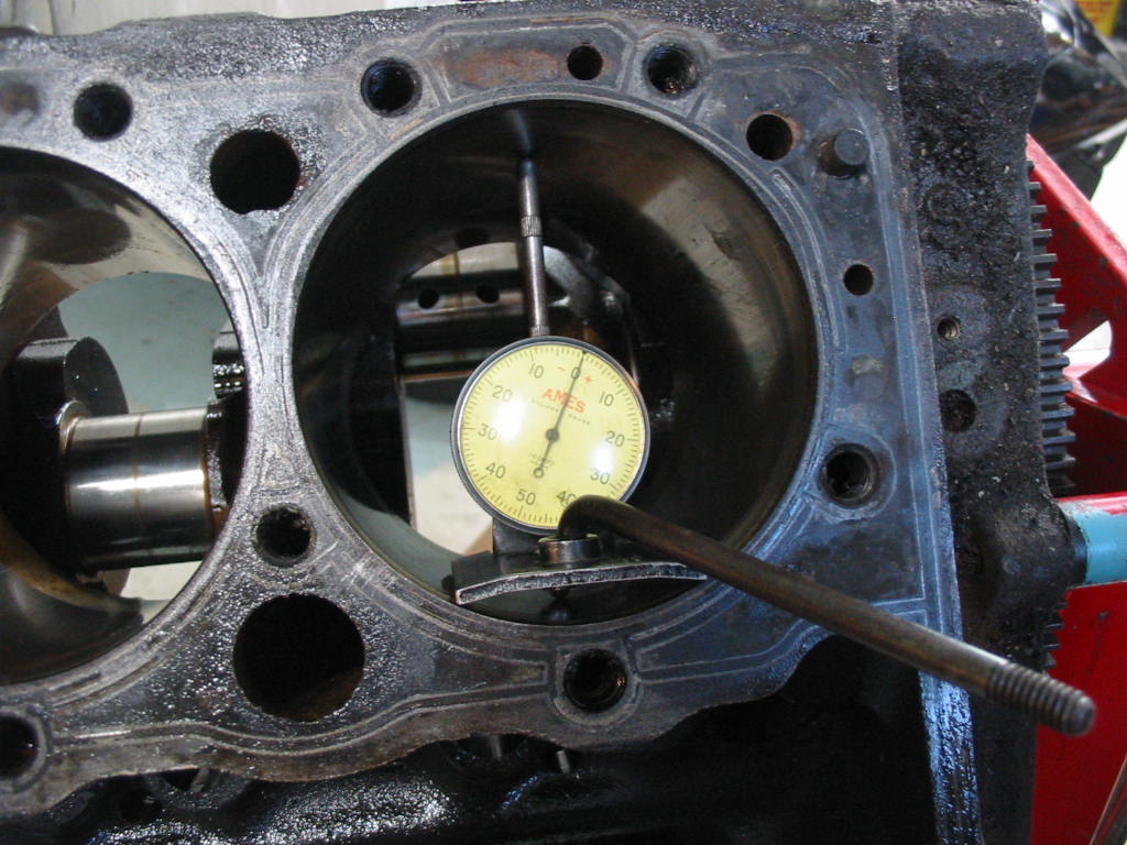
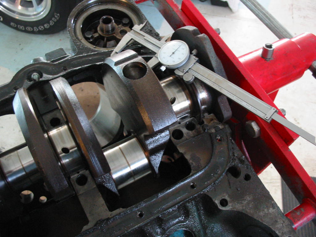
Arnold Legrow an old mechanic who passed away some years ago, knew I was interested in engine building and he kindly gave me this handy tool I can use to measure cylinder taper and bore out-of-round. The taper limit is 0.002 – 0.003 and all the bores were 0.002 or less. The out-of-round came to less than the .014 for 4″ cylinders based on 0.0035 per inch of bore. So all OK with the worst being 0.002 at the top of cylinder #7.
The pistons measured 0.002″ under 4″ so standard pistons. This is all very confusing since the car is supposed to have 144k km! Either the engine has been changed at some point or the car really only has 44k km. The block still has the remains of the GM corporate blue paint on the block that was correct for the ’79 models. The car supposedly sat for 20 prior to 2022 so it was only driven from ’79 to 2002 or 23 years of driving which is a long time to put only 44k km on the dial. So all very confusing and I’ll likely never know the history as I don’t have the contacts to check.
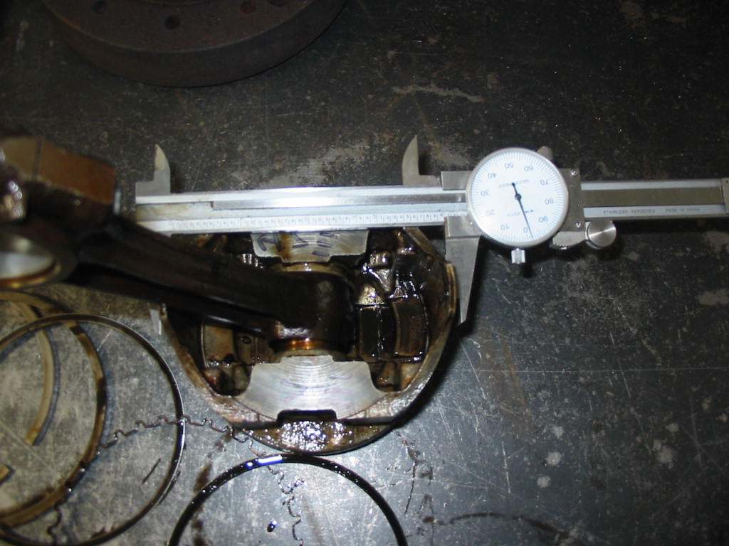
My machinist caliper is only a 2″ unit so I couldn’t use it for the crank. But the best I can figure is that the rod journals are standard at 2.1″ and the mains at 2.447. So good news here. So far it looks like an engine block refresh only needed. I’ll change to flat top pistons and also install a slightly better camshaft. and new lifters.
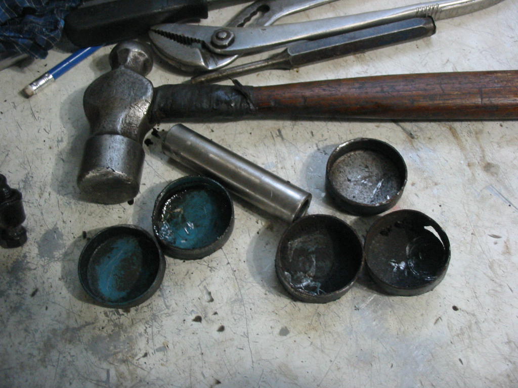
I’ve decided to remove all the frost plugs. The last thing I need is for one to start leaking after I have the engine back in the Chevy. They are all showing some serious pitting on the inside edge of the lips. I had to use an old piston pin – it has a sharp edge – to rap on the outside lip of the frost plug to get them loose. They tended to fall into the block, but were easy to take out. When I tried to tap on the inside of the plugs they just split.
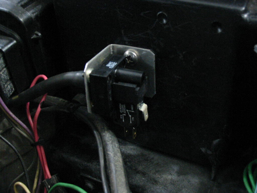
Meanwhile I’m still trying to get the bugs out of the 305 install. One issue is that the original vacuum switch and vacuum delay aren’t working as I would like. The Chevy locks up too soon after going into 3rd gear.
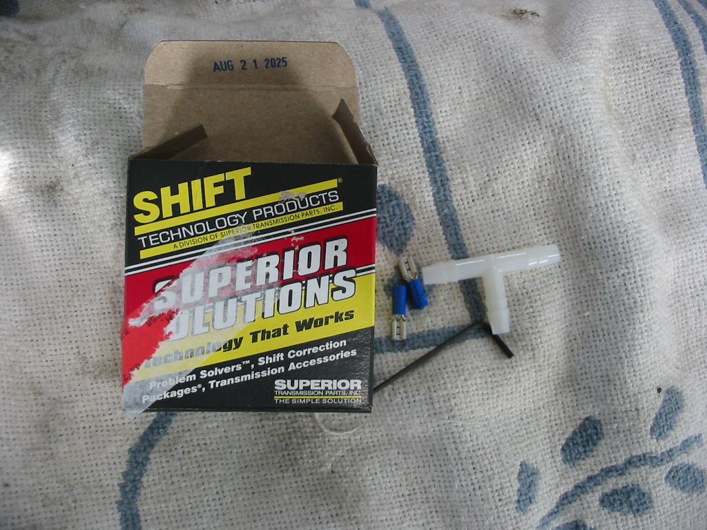
The problem I think is in the vacuum delay unit. These are, as my friend Jim Bartley says, unobtainium – no longer being made by GM. I looked at a number of replacements, but couldn’t be sure they would work. I came across this unit which says it is for non-computerized transmissions like the TH350c, 700R4, etc.
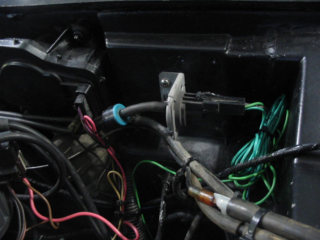
It doesn’t have a vacuum delay, but rather works by the level of vacuum coming from the intake. It can be adjusted up or down to suit the application. I’m thinking that setting it for a bit higher vacuum will delay when it engages thus allowing the car to speed up a bit more in 3rd before engaging the lockup. I had to make up a little aluminum bracket that I was able to mount in the holes I had made in the firewall for the original setup. the switch can turn on current or turn it off. I will run power to the unit and choose the connection to allow current to go to the trans when vacuum is applied.
Before I had to take the 305 off the road I did manage to see how the new lock-up switch worked. It is pretty good with its original setting. It delays some before going into lockup. I’ll increase to vacuum level a bit when I get the Chevy on the road with the rebuilt 350.
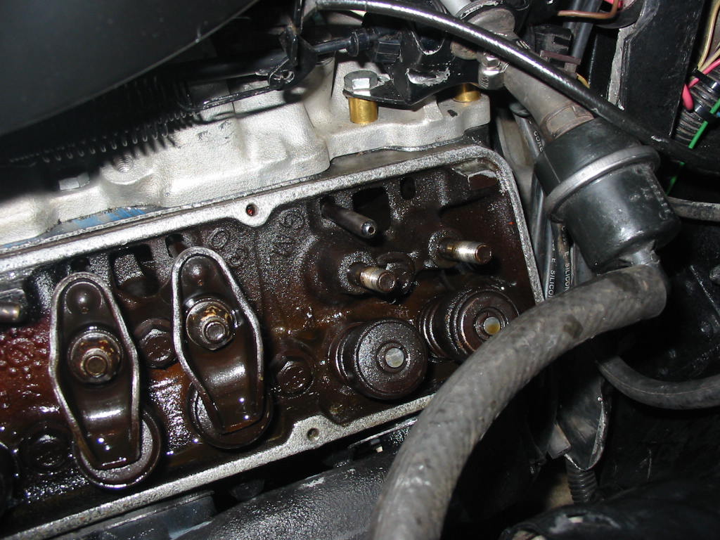
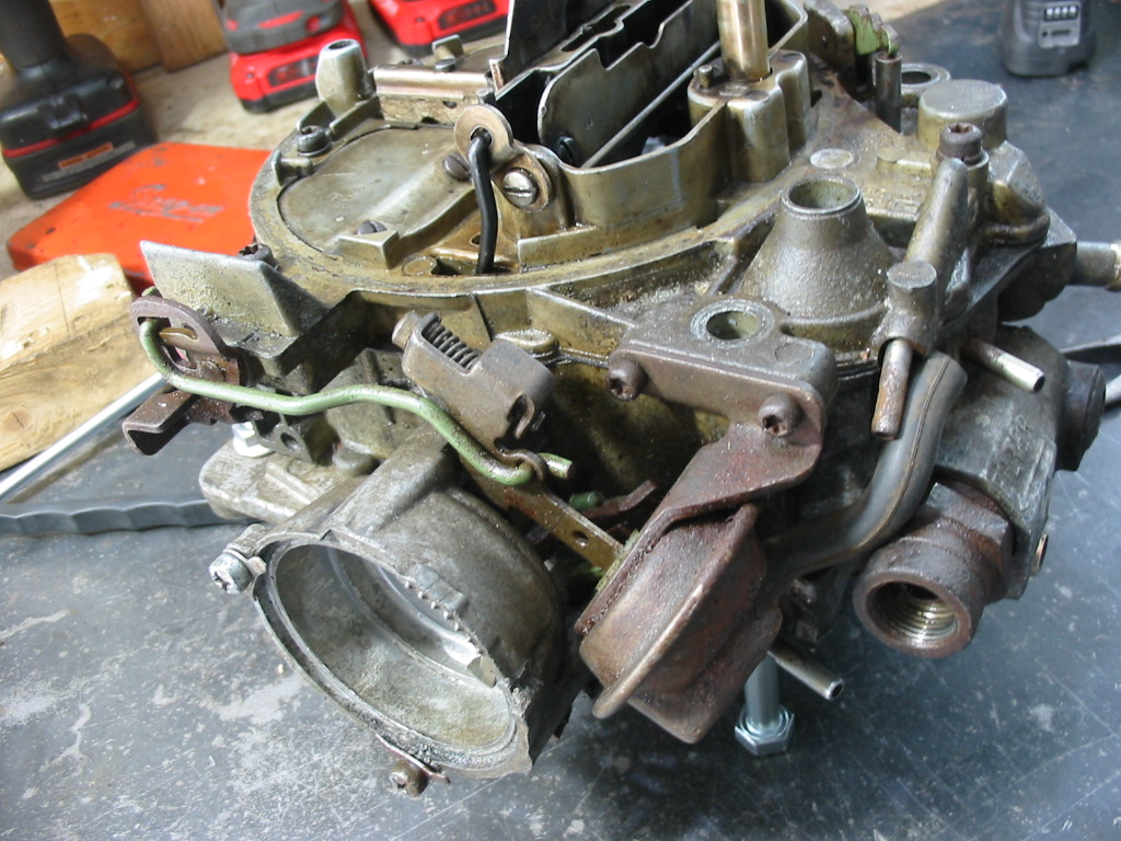
The 305 was beginning to miss and it wasn’t responding to the throttle well at all. So I thought that maybe one of the lifters might need adjusting. So I did an adjust with the engine running. All was OK until I got to #7 cylinder. The exhaust lifter at the far right was not moving a whole lot – maybe a 1/16″. My suspicion was that maybe the cam lobe for the valve was damaged.
So off with the carb and intake to see if the lifter was stuck part way up and the cam was just tickling its bottom.
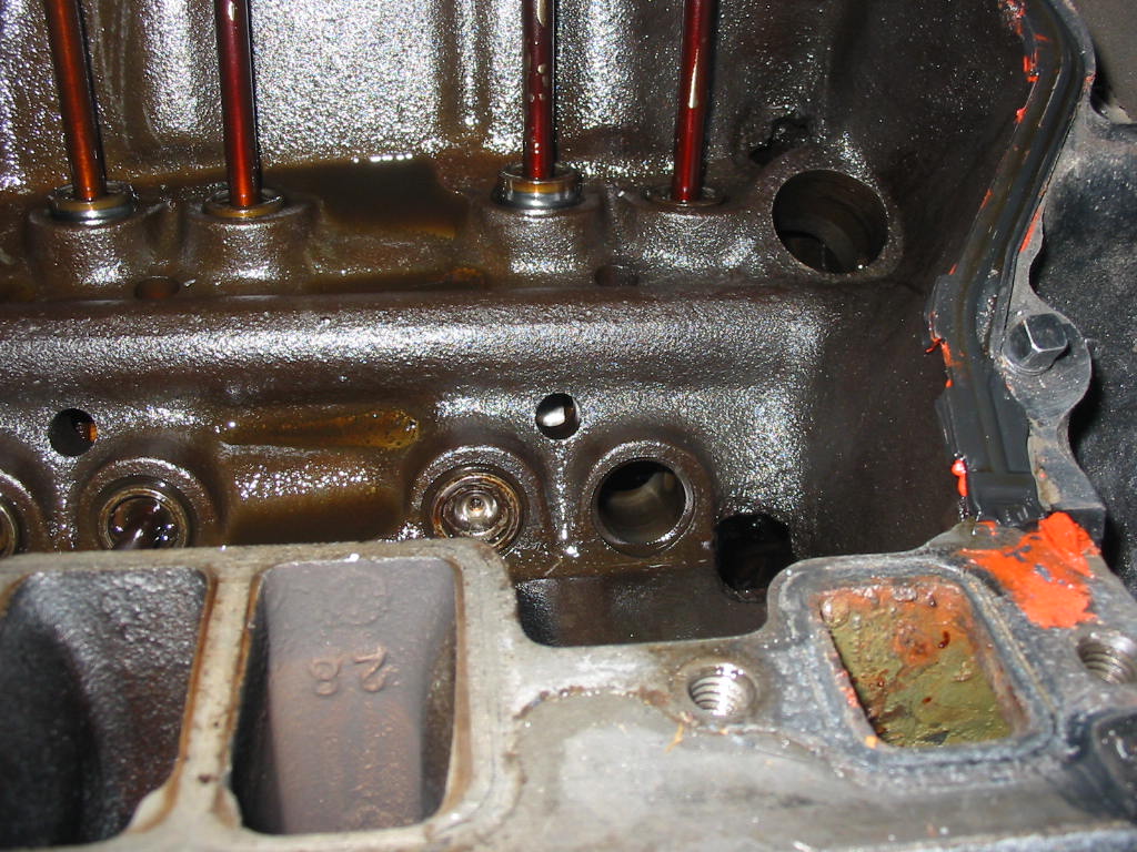
#7 exhaust lifter and it has been ground out by the cam lobe which destroyed itself in the process
Three choices: #1 install and new cam and lifters ($300+); #2 put in the 350 cam and lifters from the original Chevy motor; or #3 pull the engine and get the original 350 rebuilt and installed.
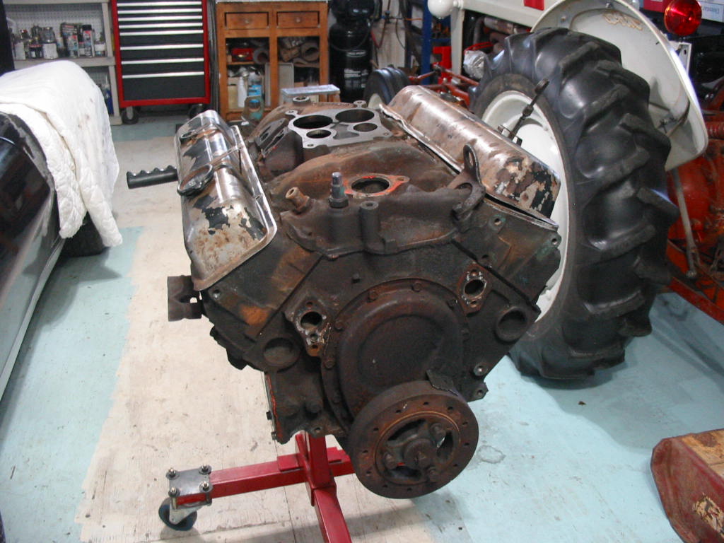
I”m going with #3 rather than using my time fixing the 305. Here the 350 is loaded on my utility trailer and I’ll be taking it to R&D Performance in Lower Onslow to be cleaned and new cam bearings installed. I was going to install the bearings myself, but I’d have to buy the tool needed plus a set of bearings and maybe two if I messed up!
Didn’t expect to have to remove the engine so soon. Oh well, it would have to have come out eventually.
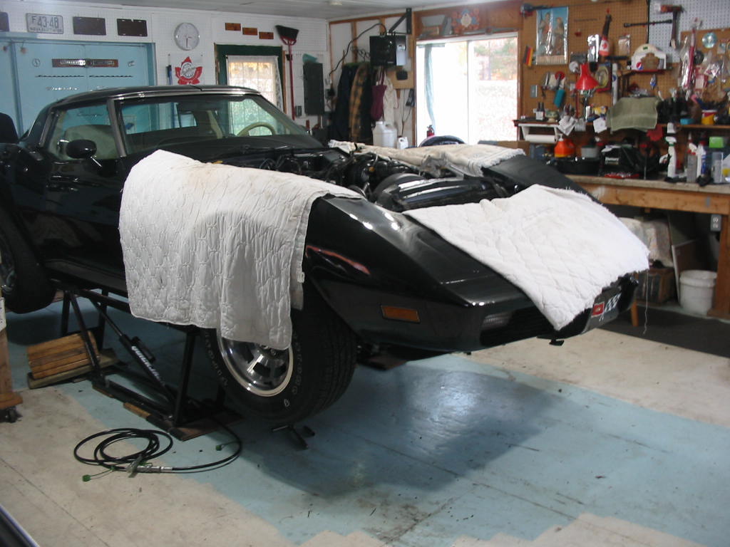
Up to the top of the quick jacks and time to get everything disconnected underneath. Not my favourite job. getting the fluids out – messy, tools dropping on my face, …
Car back down on Jack stands. I can’t fit the hoist legs under the car with them in place. Here I’m lifting the engine just enough to get the mount bolts out.
Next will be the trick of getting the engine an trans out together without damaging the body.
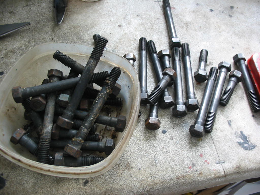
Cleaning up the head bolts with the wire wheel. The manual says to coat the threads of these head bolts with thread sealant. By the looks of them the builder dipped the whole bolts in the sealant – what a mess to clean off.
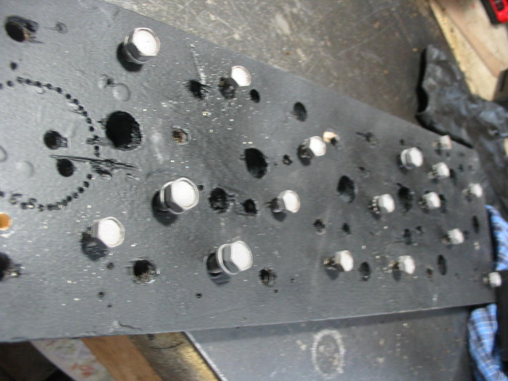
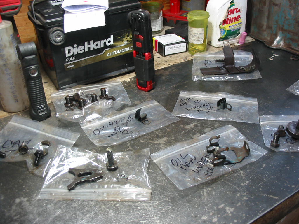
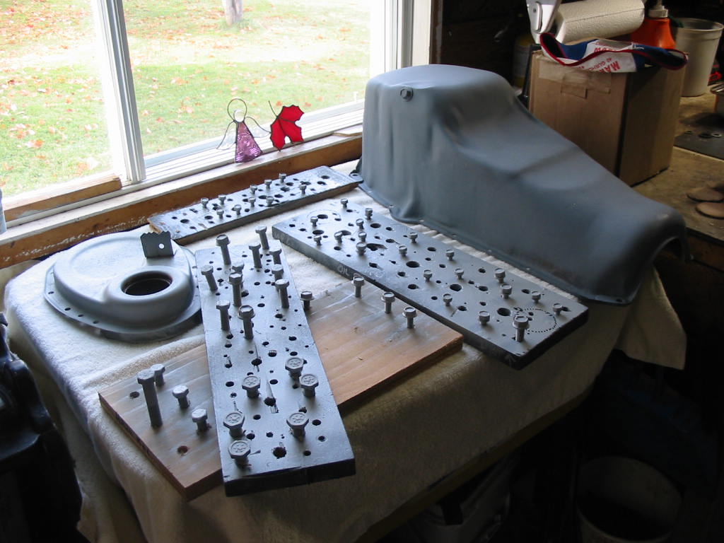
Some parts like these pan bolts I put in parts solvent and then sand blasted them before painting. I find these boards with various size holes handy to hold bolts and screws for painting.
Lots of parts to clean and some to paint. I’ll hold off painting things like the timing chain cover and pan until the engine is all together. Then I’ll give it all a good coat of GM corporate blue which is it’s original colour.
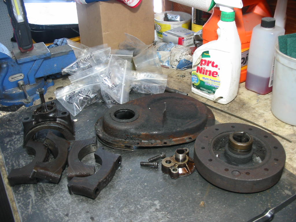
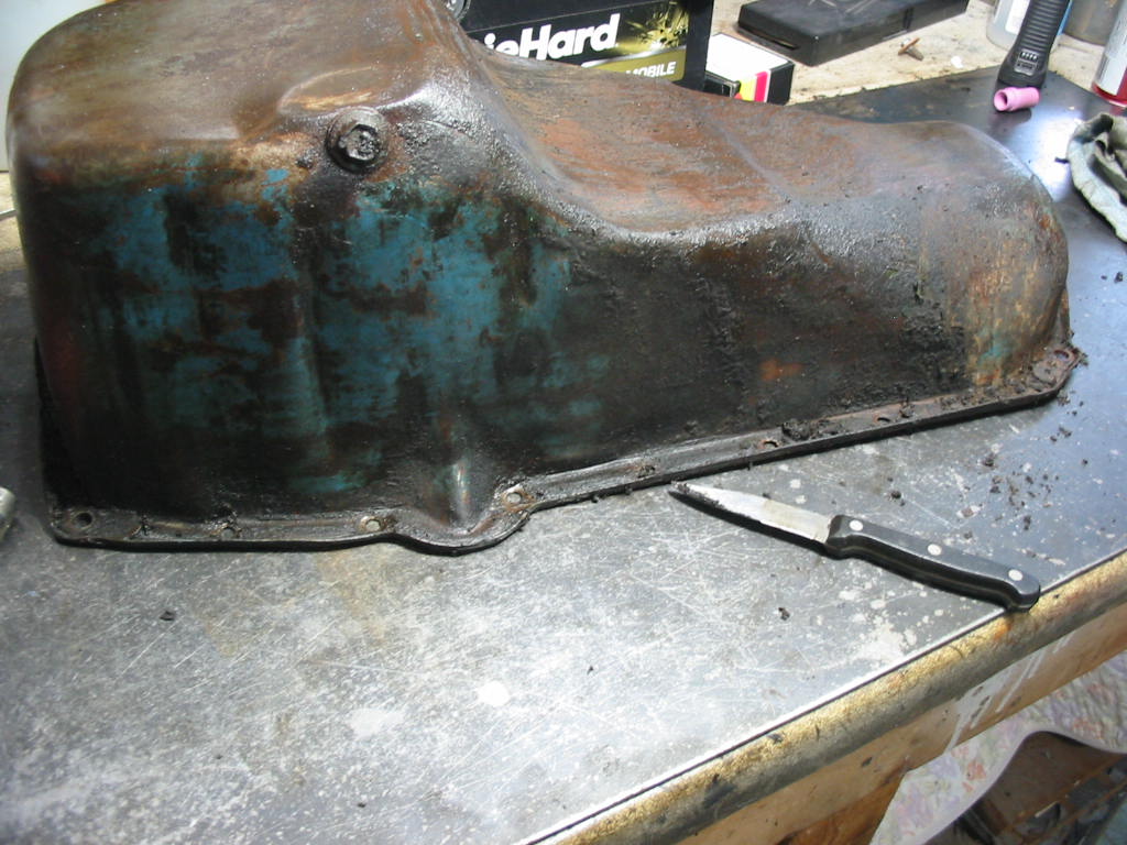
I cleaned out the residue from the rear seal using a wire wheel on my drill. I then used a dental scraper to get the remains out of the edges.
I’d have liked to put the pan in the sand blaster, but there is no way I could be sure that the all the sand was out of the inside under the baffle. Silica sand in the oil pump would not be good!
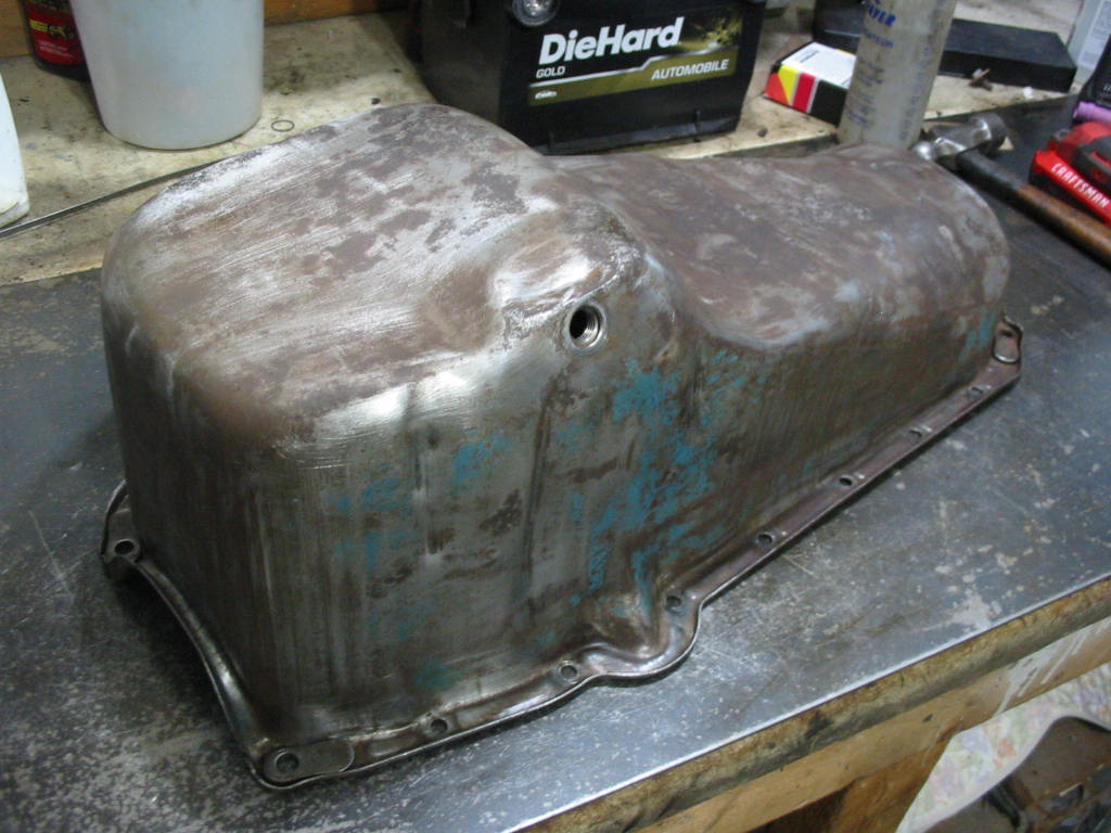
A bit of time sanding and cleaning and it’s ready for paint. I cleaned away the ‘shellac’ deposits using a scotch brite pad and some solvent.
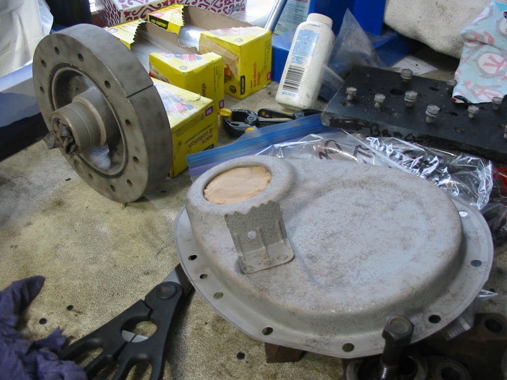
These went through the sand blaster – thankfully because the timing cover was quite pitted and the harmonic balancer has some rough casting areas.
Lots of bits and pieces to be cleaned and painted.
Look so much better with a coat of primer. Some parts will stay in prime until they are put back on the engine and the whole painted in GM corporate blue. Others will get a couple of coats of satin black.
Next: Big problems and as the saying goes ‘the best plans of mice and men…’
I’m a little out of sequence here. I meant to post this as the first in the series on the engine rebuild, but…..
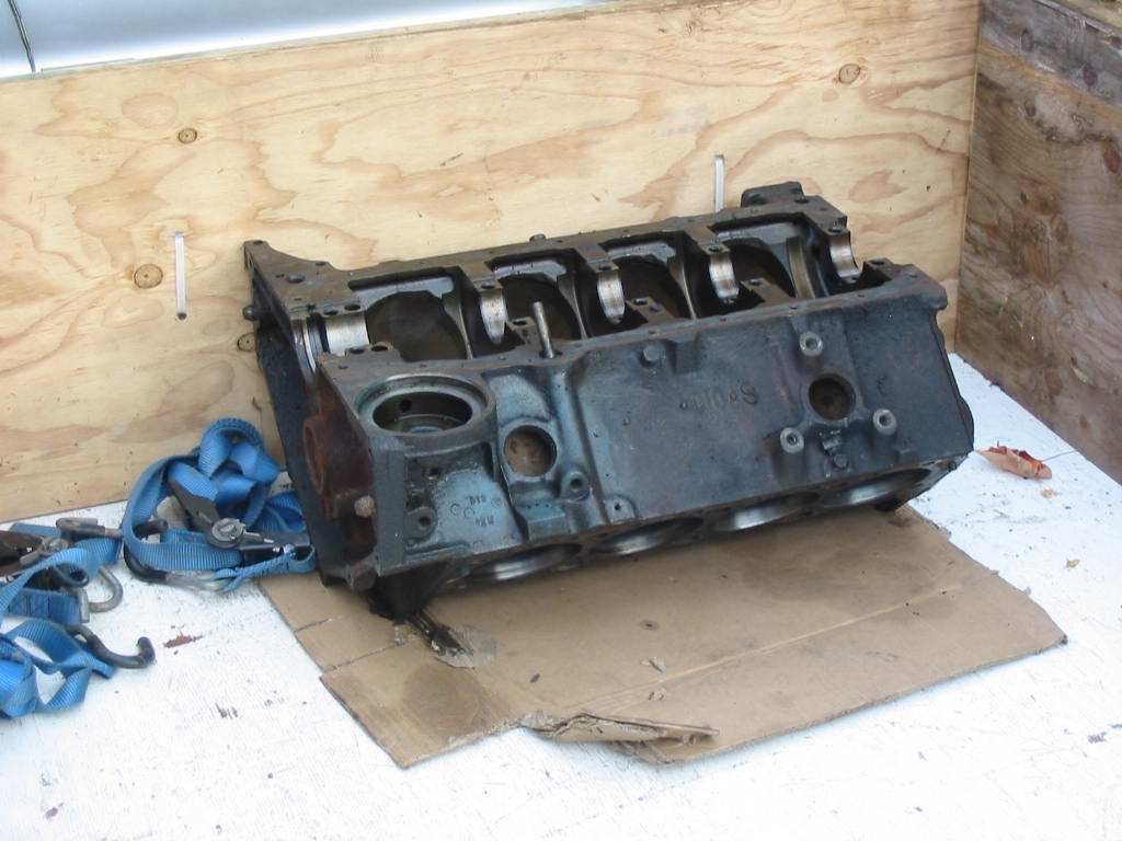
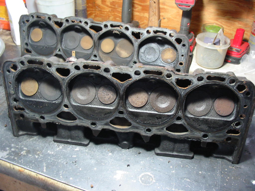
Time to tear down the original 350 and see what needs to be done.
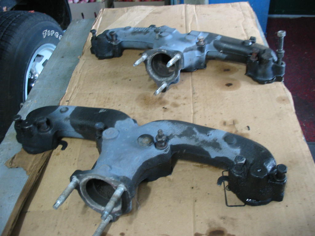
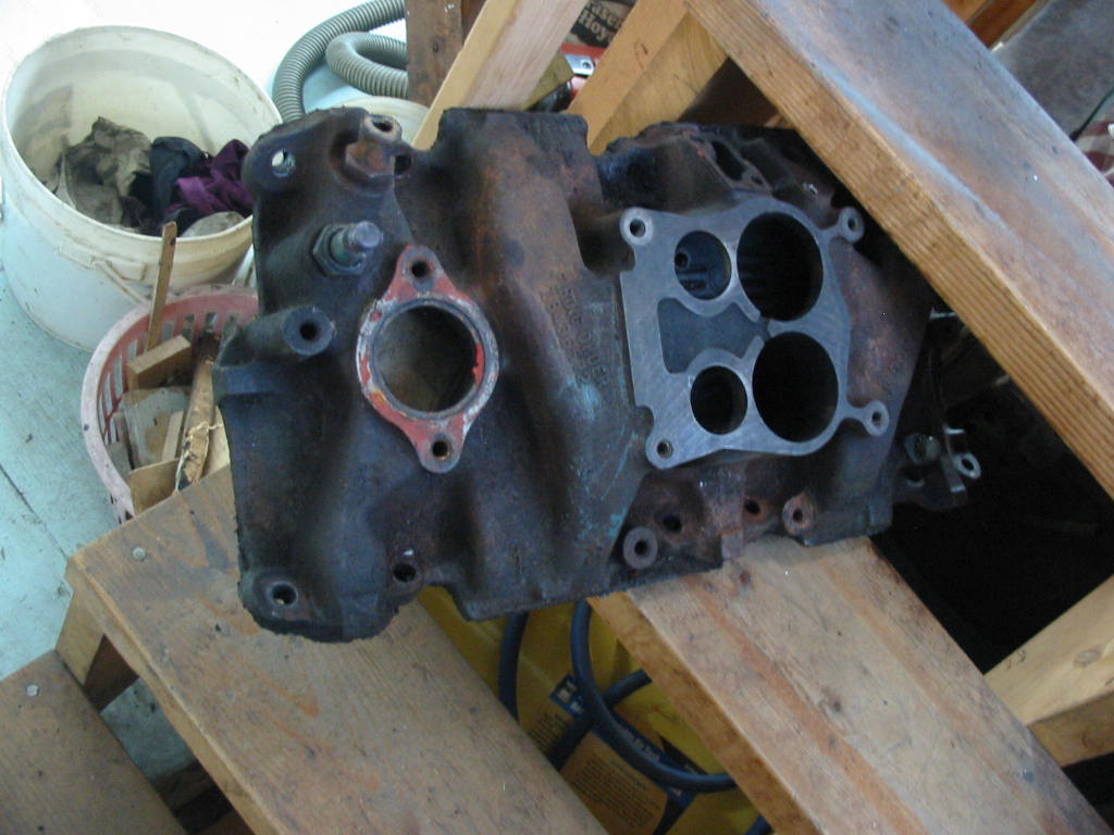
The original manifold will be replaced by an Edelbrock high rise – now on the 305 in the Chevy. I will keep it for whoever buys the car just in case they want to go back to the original intake setup.
The lifter valley looks nice and clean. Not much in the way of sludge. I did run some Seafoam cleaner through the system and that may have helped. The rust colour is not rust, but the reddish oil deposit from heated oil on hot engine parts.
Looks like all the cylinders are firing pretty good except for the one on the back head, far right. These heads are GM462824 units. They are the light casting type. I don’t want to go through the whole process of doing a valve job and magnafluxing only to have them split sometime down the road. I do have a set of Mexico GM88417368 crate engine units with the same 76 cc combustion chambers and the same valve size. I’m planning on using them.
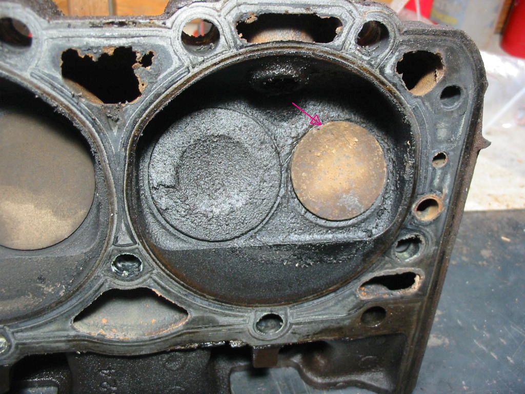
Lots of carbon and there is actually a chunk out of the intake valve (arrow).
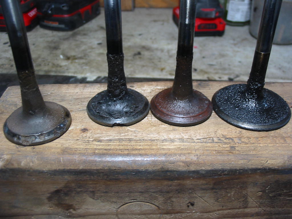
Turns out it was another intake valve that was burnt (leftmost valve) and causing the continuous misfire that was so irritating. The next one was chipped, but seems to still be firing. The next valve shows that the valves were working their way into the head. Likely caused by high speed driving with unleaded gas – ’79 heads did not have hardened seat areas. The exhaust valves show a lot of carbon (far right). Not sure why
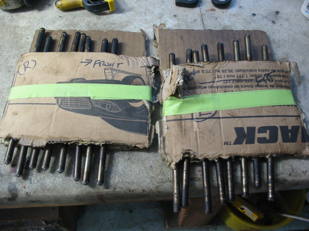
I’m keeping all the push rods and lifters in order just in case…
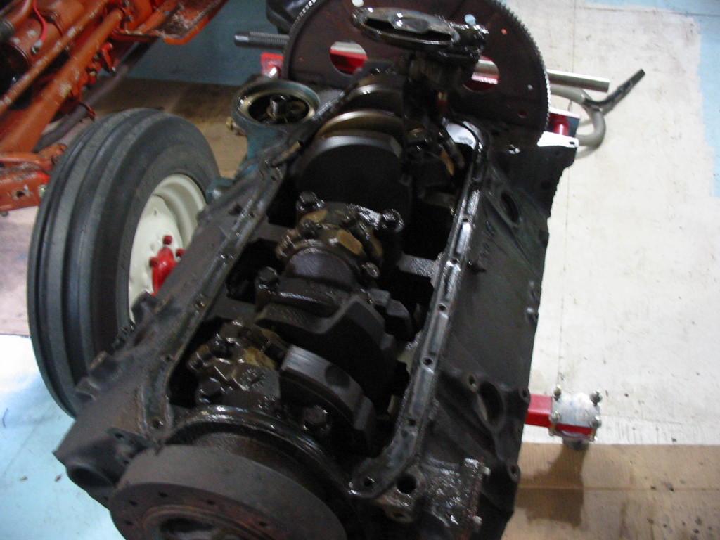
Pan off and all looks OK so far.
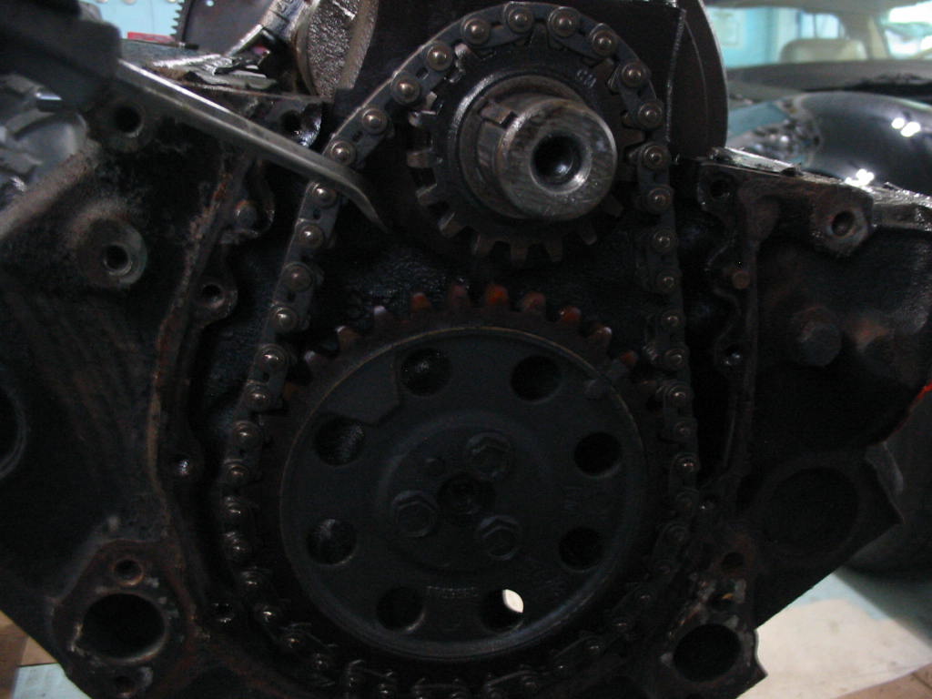
Harmonic dampener and timing chain cover off revealing a somewhat stretched timing chain.
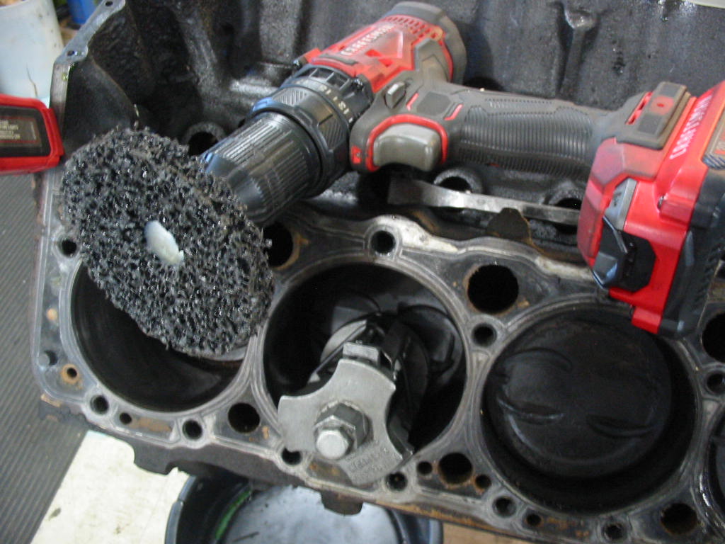
Ready to use a reamer to remove any top-of-cylinder ridges so I can get the pistons out. The paint wheel on the drill was good to remove any carbon deposits at the top of the cylinders -without damaging the cylinder wall – so I could see how thick the ridges were.
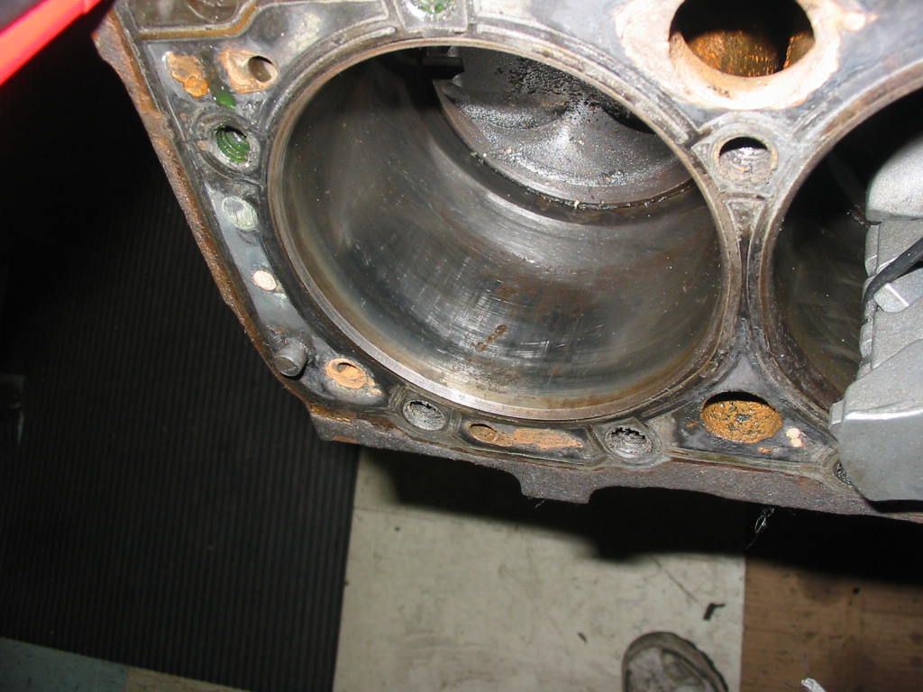
Surprisingly for an engine that is supposed to have 150k km on it there was virtually no ridges at the top of any cylinder. All the pistons came out easily once the carbon was removed with the paint stripping wheel.
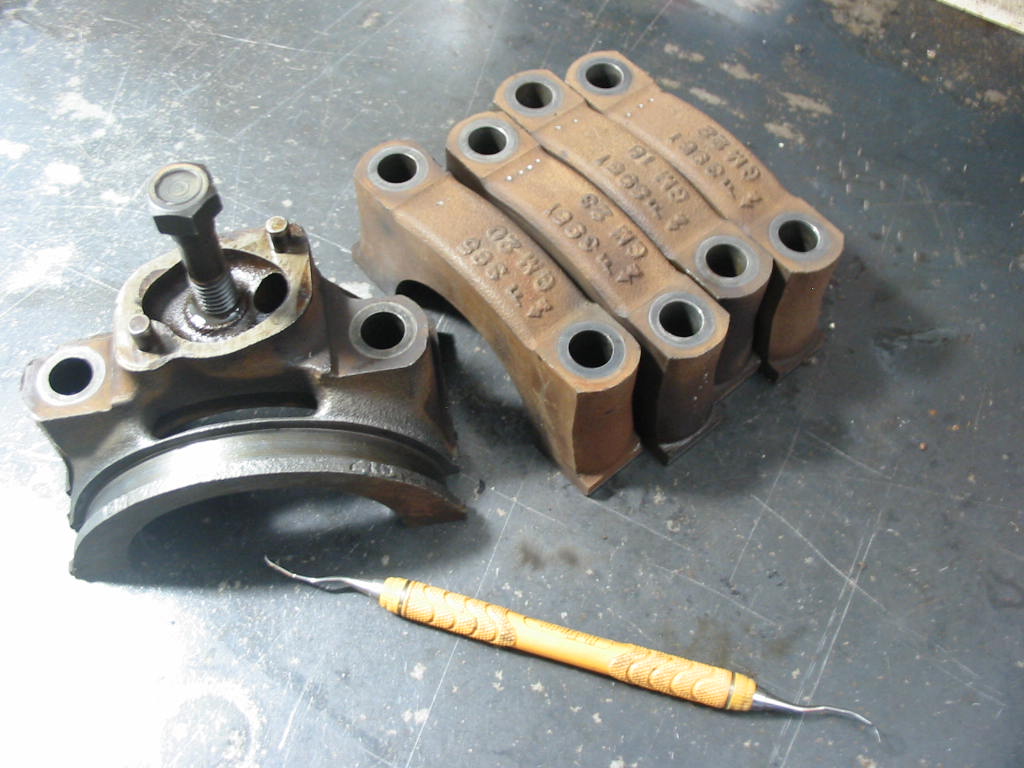
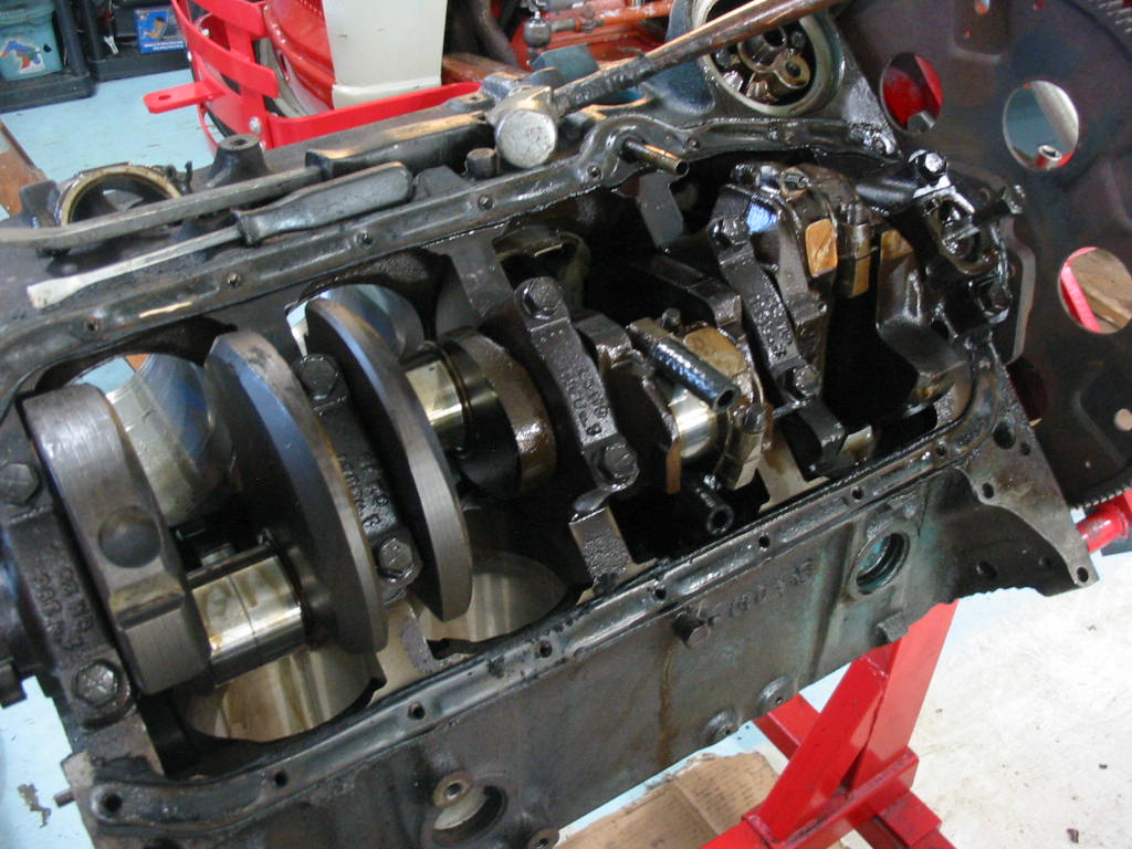
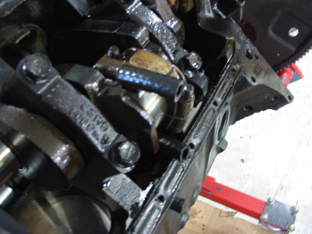
Old trick I learned years back is to put small lengths of rubber hose on the exposed rod bolts so they don’t accidentally gouge the crank journals as they pass by.
The crank journals look nice with just a bit of normal wear. I should be able to clean them up nicely with some 1500, 2500 and crocus cloth. I still need to do the measurements to see what I’ll need by way of rod journals and mains.
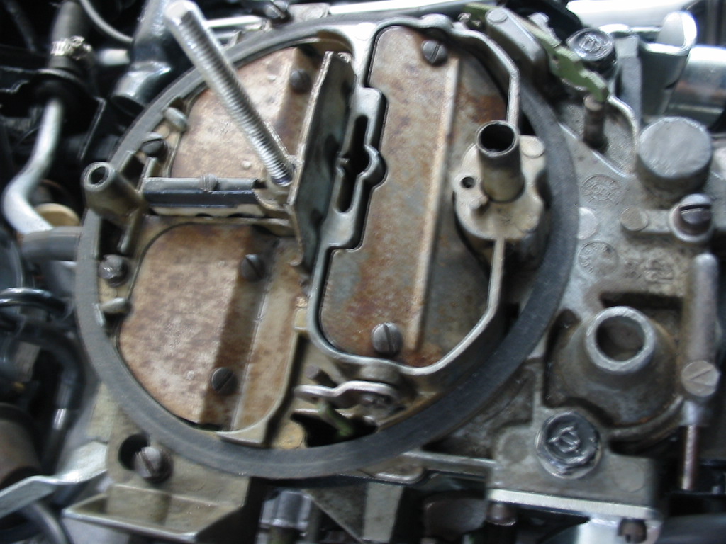
Turns out my little bend in the vacuum break arm didn’t do the trick in the end. I actually neglected to adjust the choke break when I put the carb together – funny I should have missed that.
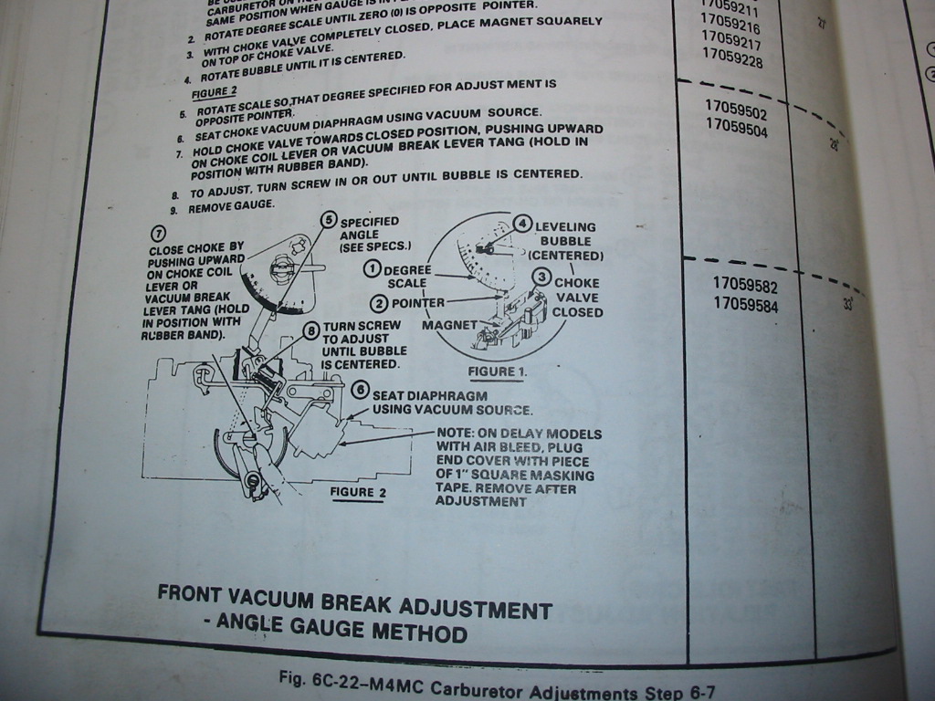
The instructions in the shop manual require a special tool to set the choke brake. This is something I don’t have and so may have put off setting it up till later….
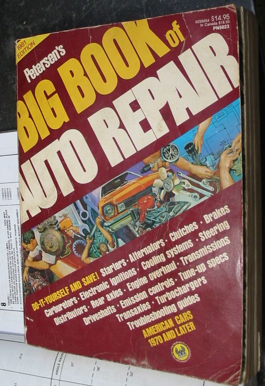
Fortunately I have an old Peterson’s manual from the era and also the old carb from the ’82 Caprice. The manual instructions didn’t require any special tools and a careful inspection of the setup on the old carb gave me an idea of what to do.
The only fuzzy area was the setting of the choke flap with vacuum put on the choke break. I don’t have the carb number so I couldn’t get the exact size for the opening at the front of the choke flap. Looking at the old carb and the numbers in the manual for all the Quadrajets I settled on 1/8″
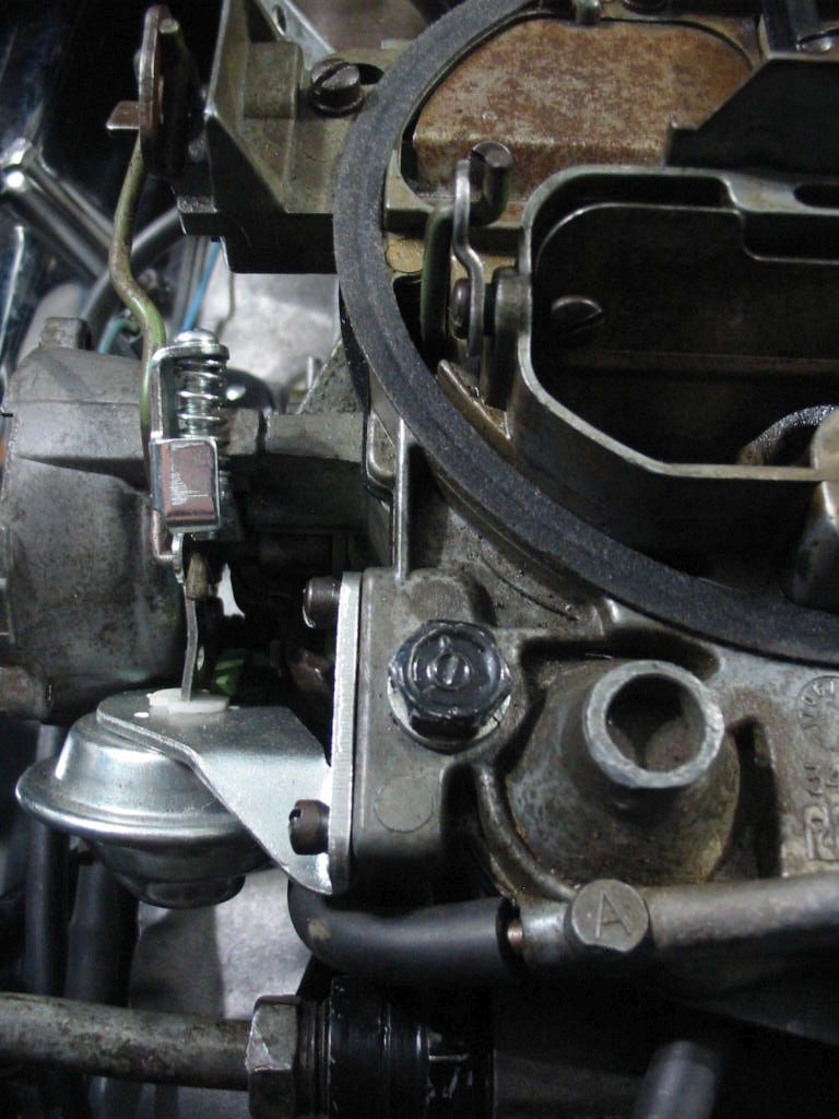
With the choke brake adjusted the actuating arm (now back to straight) clears all the linkage.
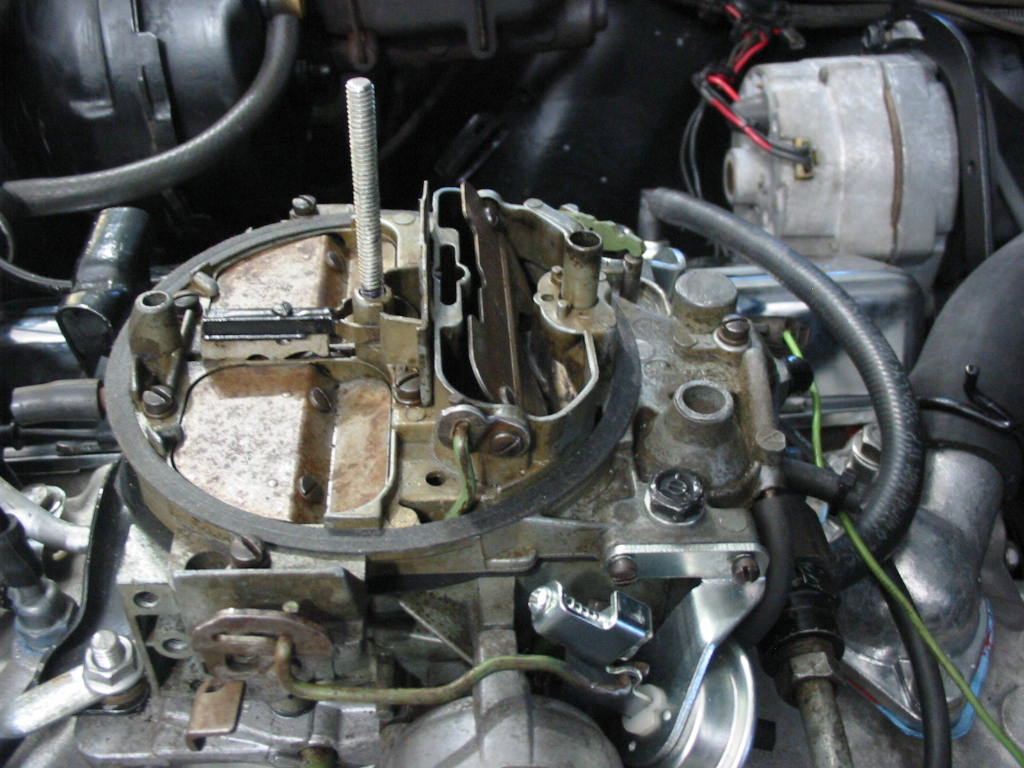
With the engine started the vacuum break opens the choke properly.
A few minutes later the electric choke allows the choke plate to move to the fully open position.
Next: Even though there may still be a few bugs to work out it’s time to start the work on the original 350.
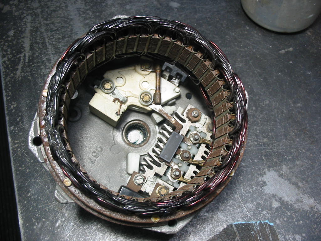
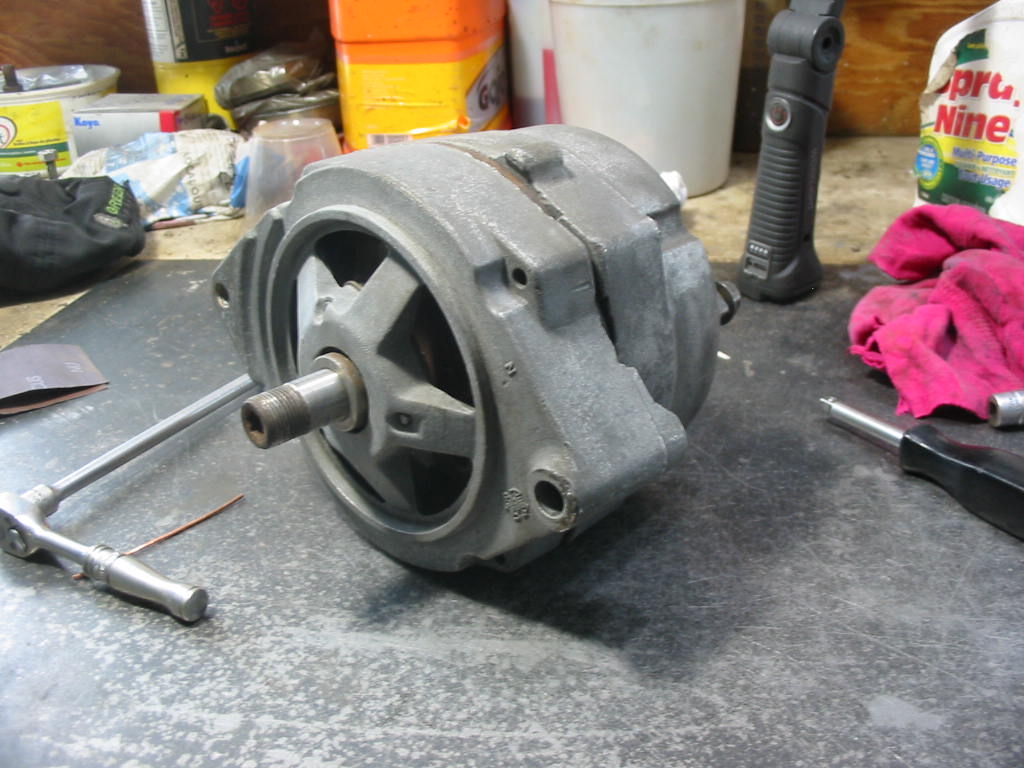
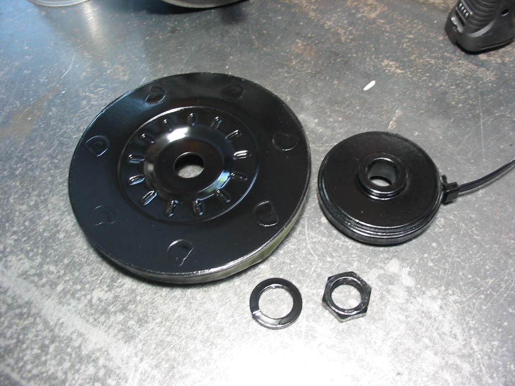
The alternator isn’t behaving itself. It shows 13+ volts when starting out, but as the engine heats up it drops the 13 and below. I have the 56 amp alternator from the ’82 Caprice. Buddy Don ran it up on his test machine and it seems to be OK and the bearings are fairly quiet. The regulator connections were a bit rusty and it’s hard to clean them in place so I opted to take the unit apart and clean up all the contacts and the corrosion on the case. The nuts and screws needed a bit of penetrating oil so they would come off easily without damaging the diode unit or regulator. I also added a tad of wheel bearing grease to the needle bearings in the back of the case.
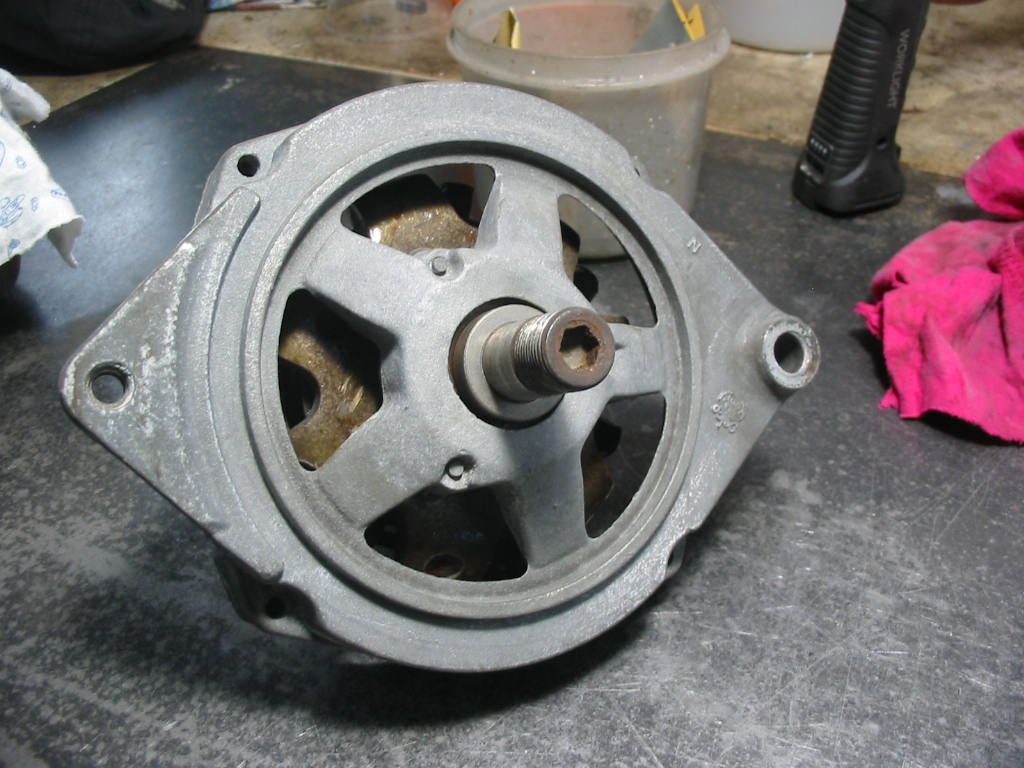
Cleaned up the front half of the unit and then fit it back together.
All nice and finished and ready to go. Sadly it wouldn’t generate from the get-go 🙁
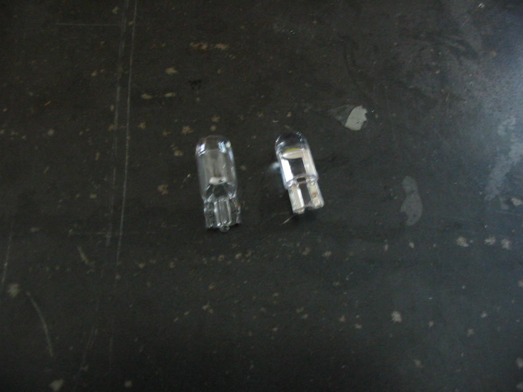
In talking to Don I remembered a side comment he made about someone changing the GEN light bulb in the dash. I then realized that I must have changed that bulb for a diode bulb when I replaced all the dash lights. The diode is on the left and the regular incandescent is on the left. With the key in the ON position I was getting a reading of about .55 volts at the R connection on the alternator (the two prong plug that goes to the alternator has a F (field) and R connectors). This is apparently not enough to trigger (excite) the alternator to start charging. After I changed the bulb I got a reading of over 2 volts and that was enough to get the alternator charging. Now there was a full 12+ volts at the R connection and the GEN light on the dash was out.
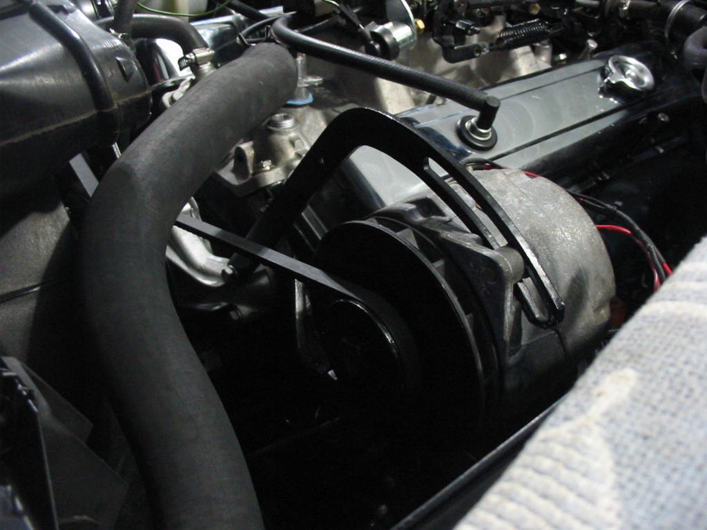
The Caprice 56 amp alternator in place and working fine.
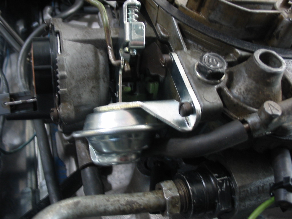
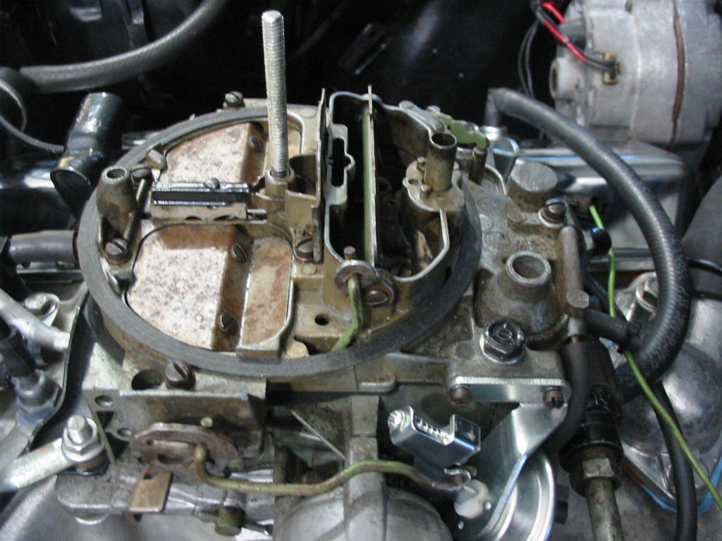
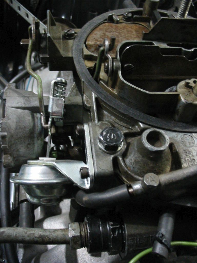
My second problem was that the choke flap wouldn’t close when I pressed the accelerator with the engine cold. I finally traced it down to the aftermarket vacuum dash pot. The linkage was getting in the way of the choke linkage. Just enough to hold the choke open until you fiddled with the choke arm.
The solution was to put a wee bend in the arm to keep it free. Once this was done the electric choke mechanism moved smoothly and the engine started and warmed up nicely.
Next: if there are no more bugs it’s time to start tearing down the original 350 🙂